A fuel level sensor is a device designed to make precise measurements of fuel level in vehicle tanks. These measurements combined with a GPS tracking and telematics platform functionality enable the following data to be harvested:
- fuel level in the tank of a vehicle
- fuel refilling
- vehicle idling
- fuel usage monitoring
- fuel theft prevention
- fuel refills or drains
- fuel consumption per time period
- average fuel consumption (miles per gallon, mpg)
Liquid level sensing technologies
For a general-purpose to detect the volume/level of fluid in a particular tank, there is a wide range of available sensing technologies, including mechanical, magnetic, pressure (hydrostatic, bubbler, differential), electrostatic (capacitive, inductive), radar and ultrasonic.

Mechanical tank sensors normally sense the position of a float, floating on the fluid, by a mechanical linkage inside/outside the tank.
Magnetic tank sensors commonly sense the position of a float by a mechanical linkage attached from a float to a magnet. Modern magnetic sensors are based on Hall effect (A phenomenon that occurs when an electric current moving through a conductor is exposed to an external magnetic field applied at a right angle, in which an electric potential develops in the conductor at a right angle to both the direction of current and the magnetic field.).
Pressure sensors family include hydrostatic, bubbler and differential sensors. A hydrostatic tank sensor typically senses the pressure of the fluid at the bottom of the tank. The amount of pressure depends upon the weight of the fluid above the sensor, which, on its turn, depends upon the amount of fluid in the tank. A bubbler sensor effectively rely on the fact that the amount of pressure required to force the air out the bottom of the tube depends upon the pressure at the bottom of the tank — a pressure that results from the amount of fluid in the tank. A differential pressure sensor detects the difference in pressure between the top and bottom of a tank, and translates that into a quantity of fluid.
Electrostatic type of sensors is represented by capacitive and inductive. By placing liquid between the electrodes the ability for the capacitor to store energy changes so the actual capacitance changes.
Ultrasonic level sensors operate by emitting a burst of sound waves in very rapid sequence. These sound waves hit the intended target, bounce back to the sensor, and travel at known speed of sound. Afterwards, time of flight can be used to calculate the distance. Radar, by contrast, works not with sound waves, but with electromagnetic waves.
Fuel Level Sensors
Various methods have been employed so far to measure fuel level: resistive film, discrete resistors, capacitive, ultrasonic, etc. Resistive-based sensors are among the most commonly used. These sensors are mechanically connected to a float which moves up or down depending on the fuel level. As the float moves, the resistance of the sensor changes, and the position of the needle changes proportional to the current flowing in the coil. A typical resistor-based FLS is shown in figure below.

The disadvantage of the resistive contact-based sensor is the wear and tear of the sensor due to the sliding contact inside the sensor elements that also leads to reduction of sensor lifetime.
The basic principle for capacity based fuel level sensing is shown on a figure below. A parallel-plate capacitor with plates that tightly adhere to the outside wall of the tank and extend to near the bottom of the tank. As the level of the fuel changes, the amount of dielectric material between the plates changes, thus producing a change in capacitance. A second capacitive sensor located near the bottom acts as a reference channel to produce ratiometric measurements. The sensor and reference capacitances are converted to digital and the data is transmitted via the I2C port to the host PC or microcontroller.

Capacitive sensors quite sensitive to changes in environmental conditions, also the measurement of capacitance is harder compare to measurement of resistance.
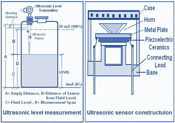
Ultrasonic waves detect an object in the similar way as Radar does. Ultrasonic uses the sound waves, and Radar uses radio waves. When ultrasonic pulse signal is targeted towards an object, it is reflected by the object and echo returns to the sender. The distance to the object is found based on the calculated ultrasonic pulse traveling time. By continuously monitoring the time between the reflected return of the pulses, the actual fluid level can be examined.

Ultrasonic Sensor is the key part of the ultrasonic transmitter device. This sensor transforms electrical energy into ultrasound waves. Piezoelectric crystals are crucial for this conversion process. Such crystals either generate electrical signals on receipt of ultrasound or oscillate at high frequencies when electric energy is applied to it. Ultrasonic fuel level sensing entail the following implementation / measurement challemges: transmitter calibration requirements, sound velocity change with air temperature variation, interference echoes.
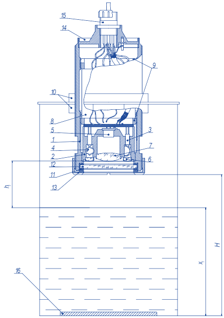
Optical techniques broadly applied in fluid flow measurements, and less common in liquids level measurements . The reason is that the measurements accuracy is affected by the factors like change of radiation sourcepower, and temperature sensitivity. However, the recent research advances in this field are targeted on reduction of the temperature error in these devices. An example of such device is given on a figure below.

The actual device consists of: 1- body, 2 - holder, 3 - LEDs 3L107B, 4 - compensating photodiodes PD-19КК, 5 - operating photodiode PD20-32К, 6, 7– lenses of a smaller and bigger diameter, 8 - printed-circuit board, 9 – inner nuts, 10 – mounting nuts, 11 - O-ring seal, 12 - safety glass, 13 - nut, 14 - collar, 15 - plug ST1-10-5-V, 16 – mirror.
Such a device enables a technique to measure the fuel level by recording the intensity value of the optical path reflected from the mirror on the reservoir bottom or another level of the reservoir. The temperature error is claimed to be within a range of 1-2%.
Here we described some of the popular fuel level sensing technologies. However, there are obviously other available techniques.Many fuel sensor manufacturers provide their devices with additional features. Some of them can be quite cutting-edge and useful. You are welcome to read more about practical aspects of fuel level sensors in our Fuel Sensor Tutorial.
Referencs
https://www.navixy.com/docs/academy/fuel-control/fuel-level-sensors-types/

